After a few prototypes using Arduino boards and AVR 8-bit microcontrollers, the current version of the charge controller is based on 32-bit STM32 ARM MCU. This change was necessary in order to be able to implement a CANopen stack. In addtion to that, the used STM32F072 allows for some additional nice features like USB or a real-time clock.
Features
- 20A MPPT charger
- 55V max PV input
- 12V or 24V battery output
- 32bit ARM MCU (STM32F072)
- CAN communication interface with standard RJ45 jacks
- USB interface for firmware update and serial monitor
- Housing for DIN rail mounting
- Expandable via Olimex Universal Extension Connector (UEXT) featuring I2C, Serial and SPI interface (e.g. used for display, WIFI communication, etc.)
- Built-in protection:
- Overvoltage
- Undervoltage
- Overcurrent
- PV short circuit
- PV reverse polarity (for max. module open circuit voltage of around 40V)
- Battery reverse polarity (destructive, fuse is blown)
Development
The charge controller is under active development and you are welcome to participate.
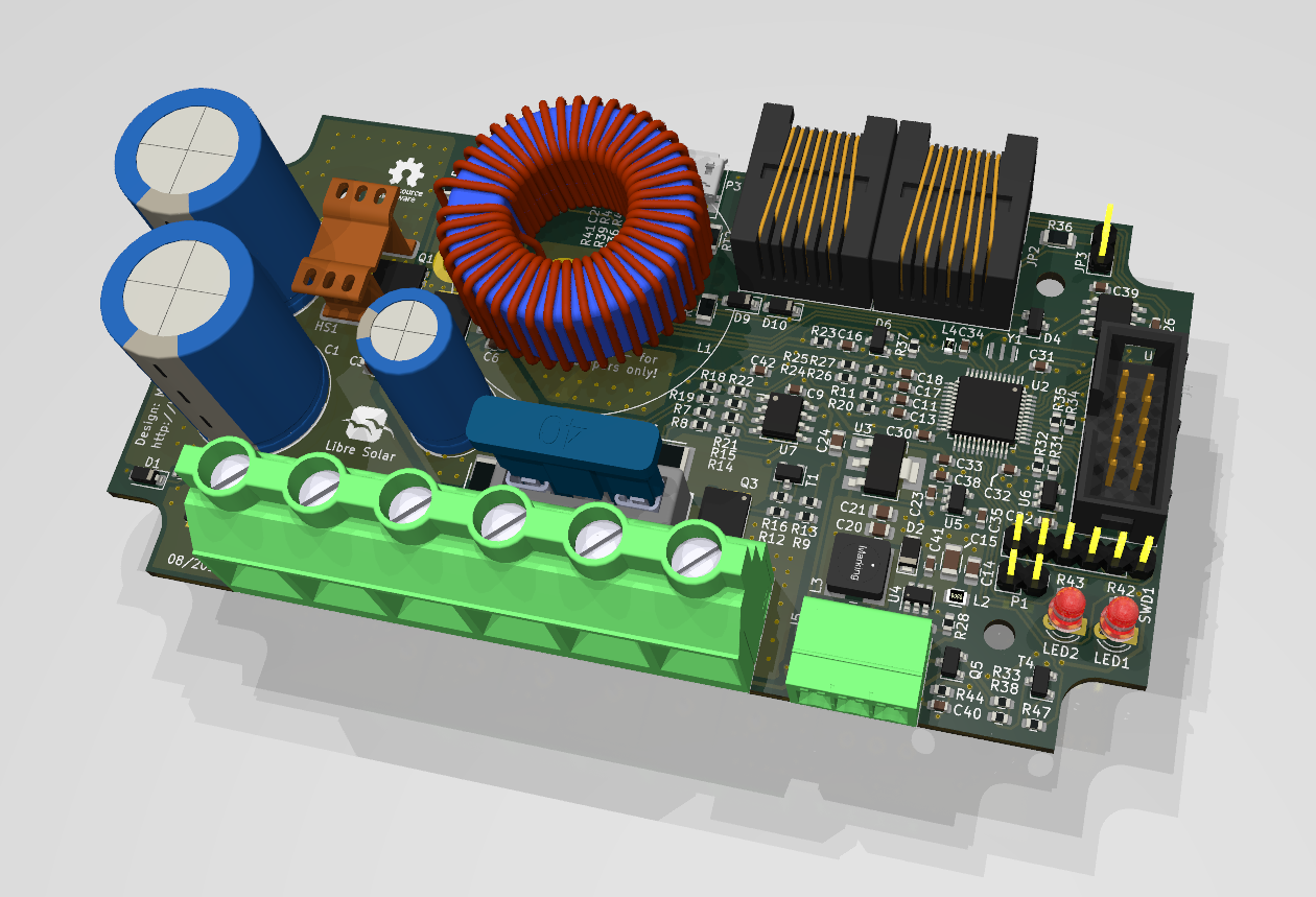
Visit the GitHub page for schematics and board layout.