
Step 2 - Creating a Stencil
| Material | Coated paper (eg. glossy magazine, Mylar or other) |
| Tools | Laser cutter, KiCAD |
| Needed Skills |
Basic PC knowledge, handling of laser cutter |
| Time | circa 60 minutes |
Starting with Production
The following steps you should do in a fablab where you find the materials and tools like a lasercutter.
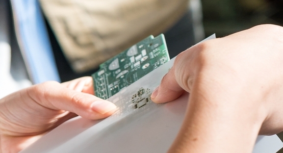
Before fitting all the small electronic parts on to the PCB we need to apply solder first. In this tutorial you learn how to create a reusable stencil which is used later to spread solder on to the whole board.
Instead of applying solder manually to every solder joint we use a laser cutter to create a stencil which can be reused if you want to prepare more than one PCB. You will fix the stencil on the board so than you can all the solder junction but nothing else - afterward you spread solder on the board which is explained in the next tutorial.
Preparing the laser cutter
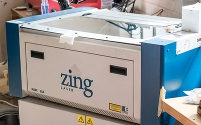
A laser cutter uses a focused high power laser to cut materials or engrave surfaces. Similar to a 3D printer or a CNC machine the laser beam is moved along two axes by a motion controller. There are software tools that generate motion commands from different file formats, in our case we use the open source software VisiCut to use the laser cutter Epilog Zing.
The two most important parameters to determine if only the surface of a material is engraved or if the material is cut through are:
- the power of the laser beam
- the speed of the beam
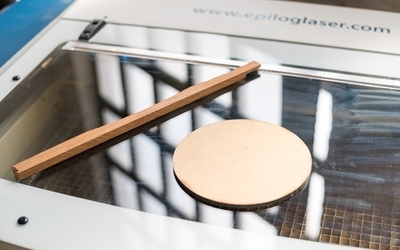
The higher the power of the beam and the longer the beam stays at one place the deeper the beam cuts into the material. If the parameters are not correct, the beam won’t cut through the material or even burn the material. Also note that different materials need different parameters to achieve the desired cut or engrave. Tests showed that coated paper from glossy magazines or a material called Mylar are a good choice for laser cutting the stencil. To find the right parameters for laser cut machine you need to perform some test cuts with different power and speed settings. Use the laser cutter template to conduct some tests by varying speed and power with a piece of material of your choice. A test scenario could look like this:
- 10% power, 100% speed
- 5% power, 100% speed
- 4% power, 100% speed
- 4% power, 50% speed
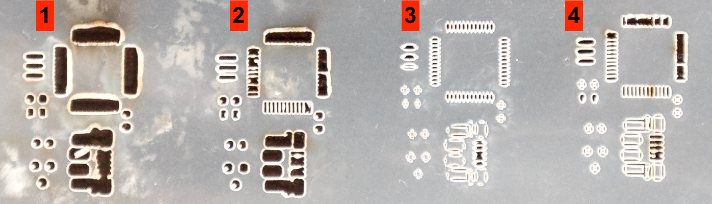
In this example the parameter set of test no. 2 was used to laser cut the stencil. In test no. 1 he fine bridges on the left side of the test cut are connected due to too much power. Tests no. 3 and 4 show that the power was not high enough to cut through some spots of the material.
KiCAD SVG export
The stencil can be created by exporting an image in SVG file format from the KiCAD board file. The process is analog to exporting a gerber file explained in the PCB production tutorial.
The new file is a vectorized graphic in SVG file format. You can open and modify the file if needed with image processing tools like Gimp or Inkscape Use the parameter settings obtained from the test cuts and create your stencil. Small spots where the laser didn’t cut through the material can be repaired using a knife.