
Step 7 - Testing of created PCB hardware
| Material | Solder, Desoldering braid |
| Tools | Soldering iron, Magnifying glass, Multimeter, Microscope (if available), Thermal camera (if available) |
| Needed Skills |
Basic electronics knowledge, calm hands, good eyes |
| Time | circa 30 minutes (if you were careful dring PCB production) |
Before you can flash the board, you should perform basic checks of the soldering process and the hardware of the board.
Solder bridges
You should carefully check if there are no solder bridges between any pins. Especially the microcontroller with its small pin pitch is susceptible to have some unwanted connections between pins.
Ideally, you use a magnifying glass or a microscope to check the board.
If you identify any solder bridges, use the desoldering braid to remove the bridges, as shown in the following picture.
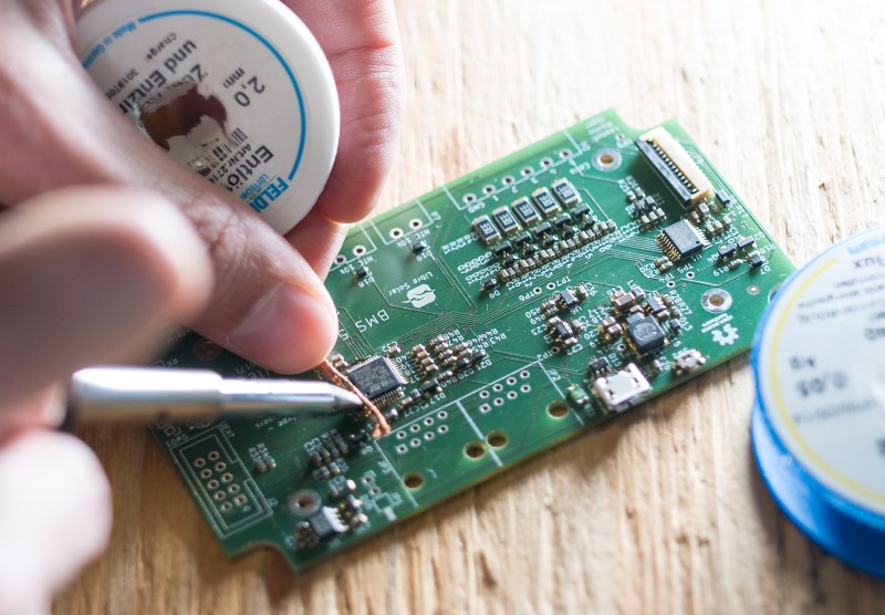
Ideally, you use a soldering tip with high mass and high temperature setting (around 400 °C) to heat up the solder quickly through the desoldering braid. You should not touch with the soldering iron for too long, so that not too much heat is transferred into the chip.
For lead-free solder, higher temperature settings might be needed. Adding a little bit of leaded solder makes it easier to remove the solder bridges.
Power supply testing
After all solder bridges have been removed and you checked that all parts in the PCB are present, you can start to power the PCB.
If the PCB has a USB connector, it is most probably the easiest way to power the board. If existing, a power LED might directly indicate that the board is working. Libre Solar boards, however, only contain LEDs which can be switched on or off by the microcontroller in order to reduce the standby power consumption. The LEDs work only after flashing the firmware.
Without an LED as indicator, you need the multimeter to check if the energy supply is working. It can be tested best using the capacitors close to the microcontroller which should be at 3.3V. An example is shown in the following picture:
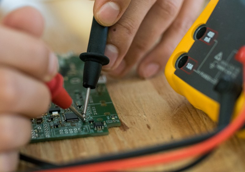
For more detailed analysis, the schematic and board files of the specific device has to be used to find possible additional points to test.
If you don’t see the correct voltage at the capacitors, something must be wrong in the PCB, possibly a short circuit somewhere.
Unfortunately, a short circuit cannot be detected easily with a multimeter. You might touch the PCB to detect if some parts get hot and look for the short circuit close to the hot parts.
If existing, you can look at the PCB using a thermal camera to detect hot spots with short circuits.
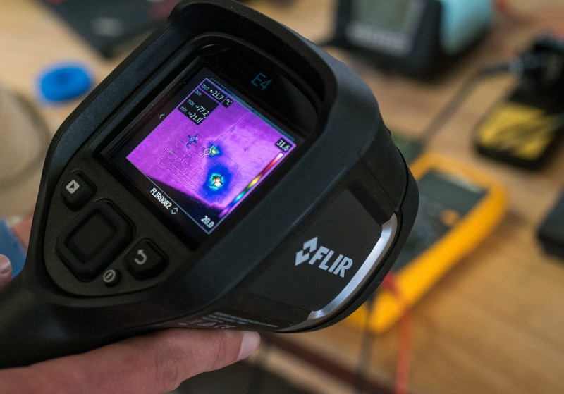
If there is a short circuit you see a red area in the thermal camera. This indicates a high current flow which let the PCB getting hot.